One of my counter parts has been having problems a CMOS checksum error with his CMA4000 OTDR . The problem manifests itself once the on board battery begins to fail.
A checksum is computed as an error-detecting code, to protect the BIOS settings stored in the CMOS memory. Each time the system is booted this number is recomputed and checked against the stored value. If they do not match, an error message is generated to tell you that the CMOS memory contents may have been corrupted and therefore some settings may be wrong
The technical description from Anritsu as to why the problem appears:
The CMA4000 and CMA4000i have a small lithium coin cell that, in the absence of power from the ACAdapter or the main battery, is used to preserve the contents of the system RAM disk as well the BIOSsettings and the real time clock. The life expectancy of this battery is approximately 5-7 years. If sufficient power is not available to preserve this memory, the unit will report a bad CMOS Checksum or System Battery failure during the Power-On Self-Test.
I’ve listed out the recovery procedure below. This is a temporary fix. To cure the problem the battery needs to be replaced.
The Recovery
-
- Insure that a proper main battery is installed in the controller.
- Connect external power from the AC Adapter. Confirm that the Battery LED indicates that the battery is charging (or is fully charged).
- Please read the following information BEFORE attempting to reset the memory. Timing is critical and success will be insured by reading this information.
a. Locate the following keys on the CMA4000 Control Panel (to the right of the LCD display):
i. F1 & F2 keys (top two soft keys)
ii. Up, down, left, right arrow keys (the plus sign (+) shaped control below the cursor knob; these are usually used to expand and contract the display)
b. Locate the following keys on the CMA4000 keyboard (below the LCD display)
i. Esc (Escape) key (upper left corner)
ii. Tab key (below the Esc key)
iii. Enter key
iv. Number keys (1-9, 0)
c. When the CMA4000 is turned on, two different text message screens are displayed. The first
is displayed by the display subsystem as it initializes. This screen is 6 lines long and reads as
follows (Note – your dates and version number may be different):

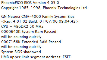
This display will be shown for about 1 second, and will quickly switch to the system Power-On
Self-Test screen (Note – your dates and version number may be different) :
 It will be necessary to press the F2 key as soon as this second (Power-On Self-Test) screen
is displayed.
- With a finger ready on the F2 key, switch the CMA4000 on and observe the screens as described
above. Immediately upon seeing the Power-On Self-Test screen, press the F2 key. After several
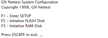
seconds, the System Configuration Menu will be displayed:
- Press the F1 Key to enter SETUP. You may receive a message stating that default values will be
loaded. Press the Enter Key to Continue. - The Bios Set-Up mode has three different screens – Main, Advanced, and Exit. On entry to
set-up mode, the Main screen is displayed. - Using the Up and Down arrow keys, move to the hours field of the System Time. Use the number
keys to enter the correct hour, then press the Tab Key to move to the minutes field. Again, use the
number keys to enter the minutes and press tab to move to the seconds field. Enter seconds if you
choose. - Use the Down arrow key to move to the month field of the System Date. Using the number and
Tab Keys, enter the proper Month, Day, and Year. Be sure to enter 4 digits for the year. - After entering the date and time, use the Right arrow key (twice) to advance to the Exit screen.
- On the Exit screen, press the down arrow key to select Save Changes & Exit.
- Press Enter. A Notice indicating that Changes have been saved will be displayed. Press Enter
again to continue. - The system will reboot normally.
As long as the main battery is kept charged, the memory should be preserved. This will permit operation until a suitable time to return the unit can be scheduled.
The original pdf of this procedure can be obtained by contacting a Optical Technical Support Engineer with the Anritsu Company.
