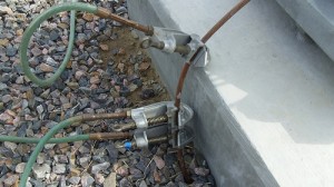
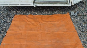
 When splicing OPGW some form of shock hazard may be present at every job site. The specific hazard may be different based on the location.
You could be at a Power Plant, Substation , Switchyard or on a transmission line. That is why it is extremely important to recognize the possible shock hazard situation for each of the different places you may find yourself in.
As should be no surprise here, there is only one requirement for a electric shock hazard and that is electrical energy. Sources of electrical energy at a work site could be in the form of electro-static charge, elctro-matic induction, accidental energization, lighting or induced voltages and current from a parallel line.
The phrase ‘personal protective grounding’ used here should be understood to mean; you taking action to secure your safety regardless of what someone else has told you. The number one rule that my fellow workers and I live by is this; If It’s NOT Grounded. It’s NOT Dead! If you follow this one rule you will be around a very long time. OPGW can easily be at a different potential than the soil at the work site. Your job site is only as safe as YOU make it.
A few electric shock hazards associated with splicing OPGW are;
- Electro-static charges
- Electro-magnetic induction
Balanced phase currents result in little induced voltage
Unbalanced fault currents produce high induced voltage
Significant ground fault current flows in the static wires
Energized power line is parallel to de-energized static wire
Ground fault currents are injected into the soil thought the tower footings
Significant Transfer Touch Hazards may exist here.
There are several things needed to create a Equal Potential Zone and each situation is different. There may be different requirements then the one’s that I will list out below. Be sure to follow ALL guidelines and recommendations set forth by the operator.
Typical Tools Used for Grounding OPGW
- Removable hot-stick
- Type 1 C-Clamps
- Protective Ground Cable – Type 1, Specifications B 172, Class K or M
- Conductive Mat

Typical OPGW Work Sites
- Wooden Transmission Structure
- Steal Transmission Structure
- Substation
Grounding a Wood Structure
When your at a wooden structure on a transmission line, after you have identified the electric shock hazard, you then establish a low-resistance work site ground. You do this by driving a temporary ground rod and bond the pole to ground. The ground road should be at least ten feet from the pole.
To establish an equal potential work zone you first bond the splice vehicle to the work ground, then install the conductive mat between the splice vehicle and the wood pole. Then bond the conductive mat to either the wooden pole or the vehicle, but not both.
The next step is to include the OPGW into the equal potential zone. First, install temporary ground cable between the work site ground and the OPGW above the storage assembly. Then install a temporary ground cable between the OPGW tails above the storage assembly or splice case.
All grounds are to be placed and removed using a removable hot-stick.
Once you have completed the Equal Potential Zone you may now proceed to touch the Optical Ground Wire
Splicing OPGW does have hazards so don’t ever let your guard down.
Be safe
